Views: 0 Author: Site Editor Publish Time: 2026-08-04 Origin: Site
Thermal failure in high-density electronic, industrial, and automotive systems carries severe operational consequences. Unmanaged heat destroys sensitive components, forces unplanned downtime, and degrades overall system performance. The core engineering challenge lies in managing thermal spreading resistance. You must maintain precise temperature control without over-engineering the fluid conveyance system. Moving heat rapidly from concentrated micro-surfaces requires a highly optimized liquid cooling loop designed for specific thermal loads.
Specifying the correct cooling circulation pump is non-negotiable for system stability. This component ensures reliable, on-demand fluid delivery. It must align perfectly with your system architecture, fluid dynamics, and lifecycle requirements. A mismatched pump leads to energy waste, cavitation, or catastrophic seal failure. Engineers must evaluate hydraulic performance against specific thermal loads. You need a solution that balances flow rate, head pressure, and material compatibility to maintain continuous operation under extreme conditions.
System Efficiency Relies on Precise Sizing: Matching the pump’s flow rate and head pressure to the specific thermal load and system resistance prevents energy waste and premature component wear.
Fluid Compatibility Dictates Material Selection: The specific coolant used (e.g., water-glycol mixtures, dielectric fluids, refrigerants) strictly governs the required pump housing, impeller, and mechanical seal materials.
Intelligent Control is the New Standard: Modern thermal management pumps utilize variable speed drives (VSD) and PWM (Pulse Width Modulation) to supply coolant strictly on-demand, optimizing energy consumption.
Proactive Risk Mitigation: Evaluating Net Positive Suction Head (NPSH) to prevent cavitation, assessing motor cooling methods, and designing for seamless integration are critical steps to ensure long-term reliability in liquid cooling systems.
Table of Contents
Selecting the right fluid conveyance hardware starts with defining strict success criteria. You must quantify the exact thermal parameters of your application. This establishes the baseline performance expectations for the entire cooling loop. We see many systems fail in the field simply because the initial thermal load calculations were based on average, rather than peak, operating conditions.
You must first quantify the total heat dissipation required in kilowatts (kW). This metric dictates the baseline performance expectations for the pump. A higher thermal load demands a higher mass flow rate to carry the heat away effectively. You calculate this by analyzing the maximum heat output of the components during peak operation. The pump must deliver enough fluid volume to maintain the target temperature delta (ΔT) across the heat source. Undersizing the pump results in thermal throttling. Oversizing it wastes energy and increases system pressure unnecessarily.
When calculating these requirements, engineers must account for ambient temperature fluctuations. A system operating in a climate-controlled data center has vastly different baseline requirements than an outdoor EV charging station exposed to direct sunlight. You must plot the thermal load across the entire expected operating temperature range. This ensures the pump can deliver adequate flow even when the coolant viscosity changes due to temperature drops.
The pump plays a critical role in moving heat rapidly from high-flux micro-surfaces. Components like CPU/GPU cold plates and IGBT modules generate intense localized heat. Thermal spreading resistance occurs when heat moves from these small components to larger heat exchangers or radiators. The fluid velocity must be high enough to break down the thermal boundary layer inside the micro-channels. A highly efficient pump ensures turbulent flow, which maximizes heat transfer rates and prevents localized hot spots.
Achieving turbulent flow requires overcoming significant pressure drops. Micro-channels in modern cold plates are incredibly restrictive. The pump must generate sufficient head pressure to push the fluid through these narrow passages without stalling. If the flow remains laminar, the fluid acts as an insulator rather than a conductor, leading to rapid component failure. We always recommend verifying the Reynolds number for the fluid at the expected flow rate to guarantee turbulence.
Mission-critical applications demand rigorous evaluation of Mean Time Between Failures (MTBF). You must frame the pump evaluation around maintenance intervals and the cost of downtime. In data centers or medical imaging equipment, pump failure means immediate system shutdown. Evaluate the wear characteristics of bearings, seals, and motors. Specify pumps rated for continuous duty cycles. Consider the accessibility of the pump for field servicing. Designing for high uptime often justifies selecting more robust materials upfront.
Field maintenance schedules should dictate your component selection. If a pump is buried deep within a server chassis, replacing a worn mechanical seal becomes a major operation. In these scenarios, specifying a sealless magnetic drive pump extends the maintenance interval significantly. You must align the pump's expected lifespan with the overall lifecycle of the equipment it cools.
Pump architecture determines how fluid moves through the cooling circuit. Different designs offer distinct advantages regarding pressure, flow, and integration. Selecting the wrong architecture guarantees poor performance and early failure.
Centrifugal pumps dominate general liquid cooling systems. They are highly suitable for high-flow, low-to-medium pressure applications. An impeller accelerates the fluid, converting kinetic energy into pressure. They handle water-glycol mixtures well and offer smooth, continuous flow. Their simple design makes them reliable for continuous duty cycles in standard HVAC and industrial cooling loops.
Positive displacement pumps serve use cases requiring high pressure or precise dosing. They trap a fixed volume of fluid and force it into the discharge pipe. These are ideal for handling highly viscous thermal fluids or pushing coolant through highly restrictive micro-channel cold plates. They maintain a constant flow rate regardless of system pressure variations. We often specify gear pumps or vane pumps when the system resistance curve is exceptionally steep.
Wet-rotor pumps utilize a glandless design. The pumped coolant lubricates the bearings and cools the motor internally. This architecture eliminates the need for a dynamic shaft seal, removing a primary leak path. However, it introduces motor heat back into the fluid loop, which you must account for in your thermal calculations. They are exceptionally quiet, making them ideal for noise-sensitive environments.
Dry-rotor alternatives isolate the motor from the fluid. They require external motor cooling fans or ambient air cooling. This design prevents process fluid temperature rise from motor heat. They rely on mechanical seals to prevent leaks, requiring careful material selection based on the coolant type. Dry-rotor pumps generally offer higher hydraulic efficiencies and can handle higher fluid temperatures since the motor is thermally isolated.
The industry is shifting from continuous-operation pumps to intelligent, ECU/PLC-controlled units. A modern thermal management pump adjusts flow based on real-time thermal sensor data. Variable speed integration allows the pump to ramp up during peak loads and slow down during idle periods. This dynamic response prevents overcooling and reduces mechanical wear on the system components.
Compare the initial capital expenditure against long-term operational savings. Intelligent pumps cost more upfront. However, they drastically reduce power consumption over the system's lifespan. They also reduce mechanical wear by avoiding constant full-speed operation. Implementing PWM control allows the main system controller to dictate exact flow rates, creating a highly responsive thermal management loop.
Standardized, off-the-shelf pumps offer rapid prototyping advantages. They are cost-effective for standard industrial cooling applications with predictable parameters. They provide proven reliability and immediate availability. For many standard water-glycol loops, an off-the-shelf centrifugal pump meets all performance criteria without the need for extended lead times.
Custom-designed thermal management solutions become mandatory under strict constraints. Severe space limitations, extreme operating temperatures, or unique dielectric fluids require bespoke engineering. Custom pumps optimize the form factor, mounting points, and hydraulic performance for a specific OEM application. When designing aerospace or military cooling systems, custom housing materials and specialized motor windings are often required to meet strict environmental standards.
Evaluating a pump requires a deep dive into hydraulic performance and material science. You must match the hardware to the specific physics of your cooling loop. Guesswork here leads to system failure.
Detail the relationship between required flow rate, fluid specific heat capacity, and the target ΔT. The formula Q = m * c * ΔT guides this calculation. You must map the pump's performance curve against the total pressure drop of the cooling circuit. Calculate friction loss through micro-channels, cold plates, hoses, and heat exchangers. The intersection of the pump curve and the system resistance curve dictates the actual operating point.
Engineers must also account for the degradation of system performance over time. Heat exchangers foul, and filters clog, which increases system resistance. You should select a pump that operates slightly to the left of its best efficiency point (BEP) on the performance curve. This provides a pressure reserve, ensuring the pump can still deliver adequate flow as the system ages and resistance increases.
Evaluate wetted materials against specific coolants to prevent galvanic corrosion and seal degradation. Stainless steel, specialized engineered plastics, and brass are common choices. Using incompatible materials leads to rapid seal swelling, housing corrosion, and fluid contamination.
Coolant Type | Common Applications | Recommended Pump Materials | Seal Compatibility |
|---|---|---|---|
Water-Glycol (EGW/PGW) | Industrial, Automotive, HVAC | Stainless Steel, Brass, PPS | EPDM, Viton (FKM) |
Dielectric Fluids | EV Batteries, Data Centers | Aluminum, Stainless Steel | PTFE, FFKM |
Deionized Water | Medical, Laser Cooling | High-Grade Plastics, 316 SS | EPDM (High Purity) |
Refrigerants (R134a, R744) | Active Chillers, Phase Change | Cast Iron, Carbon Steel | Neoprene, PTFE |
Extreme operating temperatures alter fluid viscosity. High viscosity at low temperatures increases motor load and decreases pump efficiency. Ensure the motor has sufficient torque for cold starts. If the fluid becomes too thick, a centrifugal pump may fail to prime or move fluid entirely, necessitating a switch to a positive displacement design.
Evaluate the physical footprint of the pump. Size, Weight, and Power (SWaP) constraints are critical in mobile, aerospace, or densely packed electronic enclosures. Discuss structural requirements to minimize noise, vibration, and harshness (NVH). Use vibration isolation mounts to prevent resonance transfer. Rigidly mounting a pump to a thin metal chassis turns the entire enclosure into a speaker, amplifying motor noise.
Address the selection of secure fluid conveyance connections. Specify leak-free, quick-disconnect (QD) couplings and barrier hoses. These ensure low flow resistance and ease of field service. Avoid standard hose barbs and worm-gear clamps in high-pressure or mission-critical loops, as they are prone to leaking under thermal cycling. Threaded fittings with O-ring face seals provide a much more robust connection.
The cooling architecture dictates the operational stress placed on the fluid conveyance components. Active systems require robust, continuous performance, while passive systems rely more on natural convection.
Active cooling systems transfer heat continuously to an external environment. This places rigorous demands on the pump. Demand-driven operation requires the pump to react instantly to thermal spikes. The motor must handle frequent speed variations without overheating. The bearings must withstand continuous duty cycles under varying loads. We specify heavy-duty industrial bearings for any pump operating in an active chiller loop.
In active systems, the pump often runs 24/7. This continuous operation accelerates wear on mechanical seals. You must implement a strict preventative maintenance schedule. Monitoring motor current draw provides early warning signs of bearing wear or seal friction, allowing you to replace the pump before a catastrophic failure occurs.
Evaluate the pump as a paired component with radiators, cold plates, and active chillers. System synergy ensures balanced fluid dynamics. The pump must provide enough head pressure to overcome the dense fin structures of modern heat exchangers. Mismatched components lead to flow bottlenecks and reduced cooling capacity.
When integrating with a chiller, the pump must handle the specific gravity and viscosity of the chilled fluid. Glycol mixtures become significantly more viscous at sub-zero temperatures. The pump motor must be sized to handle this increased mechanical load during startup. Failure to account for cold-fluid viscosity results in tripped breakers and stalled motors.
Different industries impose unique constraints on liquid cooling systems. Pump selection must adapt to these specific environmental and operational demands. A pump designed for a cleanroom will fail rapidly in a machining center.
Fast-charging infrastructure and EV battery packs generate extreme thermal loads. High-voltage cooling requires strict dielectric fluid compatibility. You need a highly reliable, intelligent coolant pump to manage rapid temperature fluctuations. The pump must operate efficiently across a wide ambient temperature range, from freezing winters to scorching summers.
Automotive applications also demand strict adherence to NVH standards. The pump must operate quietly so it does not disturb the vehicle occupants. Furthermore, the pump housing must withstand significant shock and vibration from road impacts. We typically specify ruggedized, wet-rotor designs with CAN bus communication for these applications.
Sensitive environments like MRI machines, lasers, and data center server racks demand precision and purity. Evaluate the need for leak-free, low-pulsation fluid delivery. Magnetically coupled pumps are ideal here. They eliminate dynamic seals, ensuring zero leakage and preventing fluid contamination.
In medical lasers, even minor flow pulsations can cause the laser beam to jitter. You must select a pump that delivers exceptionally smooth flow. Gear pumps or specialized centrifugal pumps with multi-vane impellers are often required to meet these strict pulsation limits. Material purity is also paramount; wetted components must not leach ions into the deionized water coolant.
Heavy-duty pumps are required for CNC machining, plastic injection molding, and large-scale manufacturing. Ruggedness and scale are the primary criteria. These pumps must handle contaminated environments, continuous high-load operation, and aggressive industrial coolants.
Industrial environments are harsh. Pumps are exposed to metal shavings, cutting fluids, and high ambient temperatures. You must specify pumps with robust cast-iron or stainless-steel housings. The motors should be totally enclosed fan-cooled (TEFC) to prevent dust and moisture ingress. Mechanical seals must feature hard faces, like silicon carbide, to resist abrasion from particulates in the coolant.
Even perfectly sized pumps fail if system integration ignores fundamental fluid dynamics. You must design proactively to mitigate operational risks. Field failures are almost always traced back to poor installation or inadequate system design.
Inadequate Net Positive Suction Head Available (NPSHa) leads to cavitation. The fluid vaporizes inside the pump, creating bubbles that collapse violently. This destroys impellers and causes catastrophic pump failure. To mitigate this, ensure adequate inlet pressure. Place the pump at the lowest point in the cooling loop. Minimize suction line restrictions.
Engineers must calculate NPSHa accurately. You must account for the vapor pressure of the specific coolant at its maximum operating temperature. As fluid temperature rises, vapor pressure increases, reducing the available NPSH. If NPSHa drops below the pump's required NPSH (NPSHr), cavitation is guaranteed. Always design the system with a safety margin of at least 1 meter of NPSH.
Coolant leaks destroy surrounding electronics and mechanical systems. Evaluate the choice between mechanical seals and sealless architectures. Magnetically driven pumps eliminate the shaft seal entirely. Choose this architecture for high-risk applications where zero leakage is mandatory.
If you must use a mechanically sealed pump, ensure the seal materials are perfectly matched to the fluid. Never run a mechanical seal dry, even for a few seconds. Dry running generates massive friction heat, shattering the seal faces instantly. Implement flow switches or pressure sensors to shut down the pump immediately if fluid flow is lost.
Air entrapment causes dry running and thermal spikes. Incorporate expansion tanks and bleed valves for proper system priming. Install flow, pressure, and temperature sensors for real-time fault diagnosis. Provide proper fitting instructions and specify specialized tools to eliminate mechanical alignment issues during installation.
Follow these steps for proper system priming and integration:
Install the pump at the lowest physical point in the cooling circuit to ensure gravity feeding.
Mount an expansion tank at the highest point in the system to collect entrained air.
Open all manual bleed valves before introducing fluid into the loop.
Fill the system slowly from the bottom up to push air out through the bleed valves.
Run the pump at a low speed initially, cycling it on and off to dislodge trapped air pockets.
Verify system pressure and flow rates against the design specifications once fully primed.
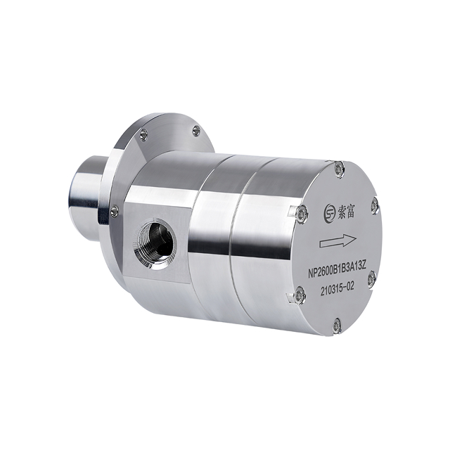
Choosing a reliable thermal management pump also requires support from a supplier with experience in coolant compatibility, precision flow control, and customized system integration. Founded in 2010, Suofu specializes in the research, development, production, and sales of micro magnetic gear pumps, providing zero-leakage, high-precision fluid handling solutions for cooling, circulation, metering, pressurization, and other demanding applications.
Selecting the optimal fluid conveyance solution requires matching hydraulic capabilities directly to your application's thermal load. You must prioritize fluid compatibility, precise flow control, and robust system integration to ensure long-term reliability. Follow these immediate next steps to finalize your system design:
Calculate your exact thermal load (kW) and map the total system pressure drop across all operating temperatures.
Cross-reference your chosen coolant with chemical compatibility charts to select the appropriate pump housing and seal materials.
Specify a variable-speed pump with PWM control to optimize energy consumption and respond dynamically to thermal spikes.
Design your physical layout to maximize NPSHa, placing the pump at the lowest point to prevent cavitation.
A: A standard water pump simply moves fluid. A dedicated thermal management pump is engineered for precise flow control, specific coolant compatibility, and integration with thermal sensors to maintain strict temperature deltas in sensitive electronics or machinery.
A: You calculate flow rate using the formula Q = m * c * ΔT. You must know the total heat load (kW), the specific heat capacity of the coolant, and the maximum allowable temperature rise (ΔT) across the heat source.
A: Incompatible fluids degrade mechanical seals, swell O-rings, and cause galvanic corrosion in the pump housing. This leads to catastrophic leaks, fluid contamination, and immediate system failure.
A: Magnetic drive pumps eliminate the dynamic shaft seal, removing the primary leak path. This ensures zero leakage, making them ideal for high-value electronics, medical equipment, and systems using expensive dielectric fluids.
A: Cavitation occurs when the pressure at the pump inlet drops below the fluid's vapor pressure. Prevent it by ensuring the Net Positive Suction Head Available (NPSHa) exceeds the pump's required NPSH (NPSHr) and minimizing suction line restrictions.
A: Wet-rotor pumps use the coolant to lubricate bearings and cool the motor, eliminating shaft seals but adding heat to the fluid. Dry-rotor pumps isolate the motor from the fluid, requiring external cooling but preventing heat transfer into the coolant loop.