Views: 0 Author: Site Editor Publish Time: 2026-08-04 Origin: Site
Industrial fluid transfer carries high stakes. Mechanical seal failures in hazardous, toxic, or corrosive applications lead to severe environmental hazards and safety risks. Traditional mechanically sealed pumps struggle with aggressive chemicals and high-temperature fluids. They suffer from fugitive emissions, demand continuous maintenance, and cause unexpected downtime. Plant engineers constantly battle these recurring issues. Complex seal flush support systems add unnecessary failure points to the fluid handling process.
The definitive sealless solution is the Magnetic Drive Pump. This technology completely eliminates the dynamic mechanical seal, removing the primary leak path found in standard centrifugal pumps. Successful deployment requires rigorous technical evaluation. You must analyze fluid properties, precise hydraulic requirements, and operational risks. Upgrading to sealless technology demands a thorough understanding of system curves and chemical compatibility to ensure long-term reliability.
Material Compatibility Dictates Lifespan: Selecting the correct wetted materials (e.g., PP, PVDF, ETFE, PFA, or specific metallic alloys) based on fluid chemistry, concentration, and temperature is the non-negotiable first step in mag drive pump selection.
Hydraulic Precision Prevents Decoupling: Accurate calculation of Total Dynamic Head (TDH), specific gravity, and viscosity is critical to sizing the magnetic coupling and preventing torque failure.
Dry-Running is the Primary Threat: While sealless designs eliminate seal leaks, they are highly susceptible to dry-run damage unless specific bearing materials (like Silicon Carbide) and active monitoring systems are implemented.
Defining a successful pump upgrade requires establishing clear operational criteria. For facilities handling dangerous media, success means achieving zero fugitive emissions. You want to extend the Mean Time Between Failures (MTBF) and reduce routine maintenance hours. Mechanically sealed pumps rely on a microscopic fluid film between two rotating seal faces. When this film breaks down due to pressure fluctuations or chemical attack, the seal fails. Process fluid then escapes into the atmosphere.
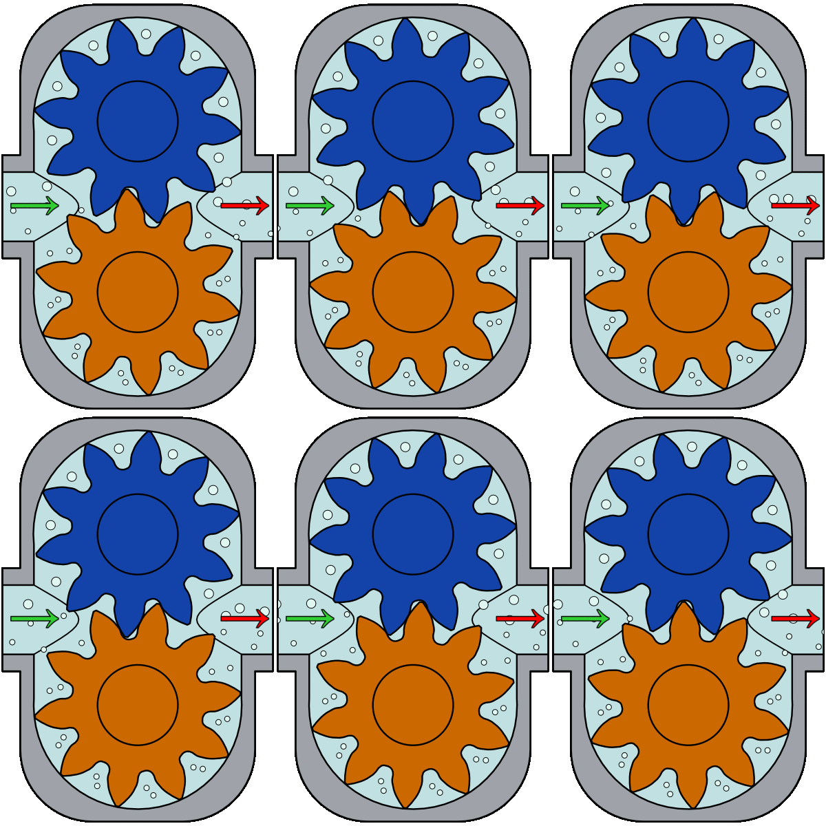
A direct comparison between mechanically sealed and sealless technologies highlights distinct mechanical differences. Traditional pumps require complex alignment and frequent seal replacements. They also need external flush plans to maintain seal integrity. A sealless pump utilizes a magnetic coupling to transmit torque from the motor to the impeller. No physical shaft penetrates the pump casing. This design simplifies installation and reduces long-term maintenance overhead by removing wear components.
Feature | Mechanically Sealed Pump | Sealless Magnetic Drive Pump |
|---|---|---|
Leakage Risk | High (dynamic seal wear) | Zero (hermetically sealed) |
Maintenance Frequency | High (seal replacements, flush plans) | Low (bearing inspections) |
Installation Complexity | Complex (requires precise alignment) | Simplified (close-coupled options) |
Environmental Compliance | Requires monitoring for fugitive emissions | Inherently compliant |
The anatomy of this equipment is engineered for absolute isolation. The physical assembly consists of a casing, an impeller mounted on an internal shaft, internal bearings, a containment shell, and the inner and outer magnet assemblies. The motor drives the outer magnet ring, creating a rotating magnetic field. This field passes through the stationary containment shell. It locks onto the inner magnet assembly, forcing the impeller to rotate synchronously. The containment shell acts as a solid barrier that isolates the process fluid from the external environment.
Specific application thresholds make mechanical seals an unacceptable liability. When pumping highly toxic, carcinogenic, flammable, or highly corrosive fluids, even minor seal weepage violates environmental regulations. Crystallizing fluids that harden upon contact with air will rapidly destroy mechanical seal faces. In these demanding scenarios, the hermetic sealing provided by magnetic coupling technology becomes an operational necessity.
The foundation of reliable operation lies in selecting the correct wetted materials. Non-metallic materials offer exceptional chemical resistance and specific temperature limits. Polypropylene (PP) provides broad resistance to mild acids and alkalis at lower temperatures. Polyvinylidene Fluoride (PVDF) handles halogens and strong acids effectively. For extreme chemical aggression, Ethylene Tetrafluoroethylene (ETFE) and Perfluoroalkoxy (PFA) linings offer nearly universal chemical inertness.
Material selections must match the hazardous fluids being handled. When processing highly corrosive acids like concentrated Sulfuric Acid or Nitric Acid, fluoropolymer linings are required to prevent rapid degradation. When handling strong caustics such as Sodium Hydroxide, specific grades of PP or PVDF may suffice. For high-pressure or extreme-temperature applications where plastics fail, metallic options like 316 Stainless Steel, Hastelloy, Alloy 20, or Titanium become necessary.
Material | Best For | Temperature Limit |
|---|---|---|
Polypropylene (PP) | Mild acids, alkalis, water treatment | Up to 180°F (82°C) |
PVDF | Halogens, strong acids, bleach | Up to 220°F (104°C) |
ETFE / PFA | Extreme corrosives, high-purity chemicals | Up to 250°F (121°C) |
Hastelloy C | High pressure, extreme temperatures, severe corrosives | Over 500°F (260°C) |
Fluid temperature directly impacts magnetic strength. Elevated temperatures can cause permanent demagnetization of the drive magnets. Neodymium magnets offer high torque transmission but are sensitive to heat, losing magnetism above 150°C. Samarium Cobalt magnets are preferred for high-temperature applications. They maintain magnetic properties at temperatures exceeding 300°C, though they are more brittle.
The containment shell material plays a role in managing localized heat generation. Metallic containment shells generate eddy currents as the magnetic field passes through the conductive metal. These eddy currents produce significant heat, which must be dissipated by the process fluid circulating within the pump. If fluid flow is insufficient, this localized heat can vaporize the liquid, leading to dry running. Non-metallic containment shells eliminate eddy current losses entirely.
Magnetic drive pumps possess severe limitations regarding particulate matter. The internal bearings rely on a clean, continuous flow of the process fluid for lubrication. Solids can easily clog the narrow internal cooling loops or scratch the precision-machined bearing surfaces. This leads to rapid catastrophic failure. These pumps are primarily designed for clean liquids.
When solids are unavoidable, strict guidelines for maximum acceptable solid sizes must be followed. Particles must be smaller than 50 microns and constitute less than 1% of the fluid volume. Specifying hardened bearing materials like Silicon Carbide is mandatory. External flushing paths using a clean, compatible liquid can be routed to the bearings to keep particulates away from sensitive internal components.
High viscosity and specific gravity dramatically increase the torque demand on the magnetic coupling. As fluid thickness or density increases, the impeller requires more rotational force. If the torque required exceeds the magnetic coupling's capacity, the magnets will decouple. The impeller stops while the motor continues spinning. Upsizing the magnetic coupling and the motor is essential when dealing with heavy or viscous fluids.
The physical configuration dictates footprint, installation complexity, and maintenance requirements. Close-coupled designs feature the outer magnet rotor mounted directly onto the motor shaft. This configuration eliminates the need for a separate bearing pedestal and flexible coupling. Close-coupled units are easier to install, require no precision shaft alignment, and fit well in space-constrained environments.
Frame-mounted designs utilize a separate pump shaft supported by its own bearing housing, connected to the motor via a flexible coupling. This heavy-duty configuration is preferred for large-scale industrial processes. It isolates the motor from pump vibrations and potential heat transfer. Frame-mounted designs facilitate easier motor maintenance, allowing technicians to remove the motor without disturbing the pump casing, though they require careful shaft alignment.
Verify baseplate levelness using a precision machinist level before mounting the frame.
Secure the pump casing to the baseplate, ensuring piping connections align without inducing pipe strain.
Perform initial cold alignment of the motor and pump shafts using a laser alignment tool.
Connect the flexible coupling and verify rotational freedom by hand.
Perform a final hot alignment check after the pump has reached operating temperature.
Standard centrifugal designs require a flooded suction. Specific applications demand specialized variations. Self-priming configurations are engineered to evacuate air from the suction line, creating a vacuum that draws the liquid up into the pump casing. These are essential for underground storage tank extraction and top-unloading of railcars. Submersible variations are entirely submerged in the process fluid, utilizing hermetically sealed motors. They are deployed in deep sumps or hazardous wastewater pits where surface mounting is impractical.
Accurate hydraulic sizing begins with mapping the system curve requirements against the manufacturer's pump performance curves. The system curve represents the friction losses and elevation changes the fluid must overcome. The pump curve shows the performance capabilities at a specific speed. The intersection of these two curves dictates the actual operating point.
Typical performance ranges accommodate capacities up to hundreds of gallons per minute and total dynamic heads exceeding 390 feet. Selecting a pump that operates near its Best Efficiency Point (BEP) is necessary. Operating too far to the left or right of the BEP induces severe radial loads on the internal shaft and bearings. This increases internal heat generation and drastically shortens the equipment's lifespan.
Understanding Net Positive Suction Head (NPSH) prevents cavitation. NPSHa (available) is the absolute pressure of the fluid at the pump suction, minus the fluid's vapor pressure. NPSHr (required) is the minimum pressure required by the pump to prevent the fluid from vaporizing as it enters the impeller eye. The system must always be designed so that NPSHa exceeds NPSHr by a safe margin.
The consequences of cavitation in a sealless pump are severe. As vapor bubbles form and collapse, they cause intense localized shockwaves that erode the impeller. Vapor lock disrupts the internal cooling and lubrication flow to the bearings. This rapid loss of lubrication leads directly to dry running, excessive heat buildup, and catastrophic internal bearing failure within minutes.
Proper motor sizing requires analyzing the relationship between horsepower, fluid specific gravity, and the required torque rating of the magnetic coupling. Water has a specific gravity of 1.0. If a chemical has a specific gravity of 1.5, it requires 50% more horsepower to pump the same volume at the same head. The magnetic coupling must be rated to handle this increased torque.
Selecting the appropriate magnet size involves applying safety factors for startup and transient conditions. During initial startup, the inertia of the fluid and the impeller creates a temporary spike in torque demand. The magnetic coupling must possess sufficient reserve strength to overcome this starting torque without breaking synchronization. This ensures reliable operation under maximum load conditions.
Dry running remains the most fatal operational risk for standard sealless pumps. The internal shaft bearings rely entirely on the process fluid for lubrication and cooling. The absence of liquid causes immediate and severe friction. Without the fluid film, the bearing surfaces grind against each other. They generate massive amounts of heat that can melt plastic components, shatter ceramic bearings, and breach the containment shell.
Specific hazards arise during batch operations, line stripping, and tank-emptying scenarios. In these situations, the pump naturally loses prime at the end of a run as the vessel empties. If the equipment is not immediately shut down, it will run dry. Operators must implement strict procedures and automated controls to prevent the pump from operating once the fluid supply is exhausted.
Selecting the right internal bearing and bushing material involves balancing chemical resistance, wear tolerance, and dry-run capabilities. Carbon Graphite is excellent for marginal lubrication situations and offers a degree of dry-run tolerance. It possesses poor chemical resistance against strong oxidizers and lacks mechanical wear resistance against abrasives.
Silicon Carbide is the industry standard for wear resistance and chemical inertness. It handles virtually any aggressive chemical. Standard Silicon Carbide is highly brittle and extremely prone to thermal shock. If a pump runs dry and heats up, and then cool fluid suddenly enters the casing, the Silicon Carbide bearings will shatter instantly. Specialized Treated or Diamond-Coated Silicon Carbide bearings offer the chemical resistance of standard ceramics while providing a significantly lower coefficient of friction to survive short-duration dry-run events.
Decoupling occurs when the required torque exceeds the magnetic coupling's rating. The outer drive magnet spins while the inner driven magnet stalls. This acts as a safety slip-clutch mechanism, preventing motor overload. Decoupling is typically triggered by sudden system blockages, pumping fluids with unexpectedly high specific gravity or viscosity, or a jammed impeller caused by solid debris.
The thermal consequences of operating a decoupled pump are severe. As the outer magnets spin past the stationary inner magnets, massive eddy currents and magnetic friction are generated. This causes rapid heat buildup within the containment shell. If the motor is not stopped immediately, this heat will melt non-metallic containment shells or boil the trapped fluid in metallic shells, leading to a dangerous pressure rupture.
Relying solely on operator intervention is insufficient for protecting this highly engineered equipment. Active instrumentation is necessary for comprehensive risk mitigation. Active power monitors are the most effective defense. They continuously measure the motor's power draw and can instantly detect the underload condition caused by dry running or the overload condition caused by decoupling, shutting down the motor in milliseconds.
Additional protection strategies include mounting temperature sensors directly on the containment shell to detect the rapid heat buildup associated with internal friction or decoupling. Flow and pressure switches installed in the discharge piping provide secondary verification that fluid is actively moving through the system. This ensures the internal cooling loops remain fully flooded.
Deploying advanced sealless technology plays a role in satisfying stringent environmental regulations. Agencies enforce strict Clean Air Act standards regarding the emission of volatile organic compounds and hazardous air pollutants. Because magnetic drive technology eliminates the dynamic shaft seal, it provides zero fugitive emissions. This ensures absolute compliance with rigid environmental mandates and protects facilities from severe regulatory fines.
Industrial deployment must adhere to recognized dimensional and performance standards to ensure seamless integration into existing piping grids. Pumps designed to ANSI B73.3 standards are utilized heavily in the North American chemical process industry. This ensures dimensional interchangeability between different manufacturers. For heavy-duty petroleum, petrochemical, and gas processes, API 685 dictates the rigorous design requirements for sealless pumps, focusing on extreme temperature and pressure containment. ISO 2858 serves as the equivalent dimensional standard for the European and global chemical processing markets.
Compile comprehensive application data including precise flow rates, total dynamic head, chemical composition, concentration percentages, and temperature ranges.
Cross-reference your fluid data against specific material compatibility charts to select the appropriate wetted materials and containment shell.
Calculate the required magnetic coupling torque based on the fluid's specific gravity and viscosity to prevent decoupling during startup.
Install active power monitors and temperature sensors to protect the internal bearings from dry-running and thermal shock.
For applications requiring precise and zero-leakage fluid transfer, Suofu is a specialized manufacturer founded in 2010, focusing on the research, development, production, and sales of micro magnetic gear pumps. Supported by proprietary technologies, customized engineering services, and experience across more than 60 industries, Suofu helps customers develop reliable fluid-handling solutions for demanding pressure, temperature, and chemical compatibility requirements.
A: These pumps typically handle viscosities up to 150-200 cP efficiently. Beyond this threshold, internal friction increases significantly, causing severe efficiency drops. Pumping highly viscous fluids requires specialized, upsized magnetic couplings and larger motors to prevent the magnets from decoupling under the heavy torque load.
A: Standard models cannot run dry without suffering catastrophic internal bearing failure due to extreme friction and heat. Models engineered with specialized diamond-coated silicon carbide or specific carbon graphite bearings, combined with active power monitoring systems, can survive short-duration dry-run events without immediate destruction.
A: Decoupling acts as a magnetic slip-clutch when the torque required to turn the impeller exceeds the magnetic coupling's strength. This failure to synchronize is usually caused by sudden discharge blockages, pumping fluids with unexpectedly high specific gravity or viscosity, or solid debris jamming the impeller.
A: Both are sealless designs, but they operate differently. A magnetic drive pump uses a standard external motor coupled to an outer magnet ring that drives an inner magnet inside a containment shell. A canned motor pump integrates the motor directly into the pump housing, with the stator and rotor separated by a thin, sealed cylinder.
A: Eddy current heating occurs when a rotating magnetic field passes through a conductive metallic containment shell. To prevent this heat generation, engineers specify non-metallic containment shells made from engineered plastics or advanced industrial ceramics, which do not conduct electricity and produce zero eddy currents.