Views: 0 Author: Site Editor Publish Time: 2026-08-04 Origin: Site
Incorrect fluid equipment specification carries severe financial and operational consequences for industrial facilities. When engineering teams miscalculate system requirements, plants face catastrophic mechanical seal failures, chronic cavitation, and excessive energy consumption. These failures usually stem from a fundamental misunderstanding of fluid dynamics in real-world applications. Process fluids rarely maintain a static state. A unit specified for a baseline fluid condition frequently struggles when operational parameters shift, exposing a massive gap between theoretical system design and actual field demands.
To prevent these failures, engineers must adopt a rigorous evaluation framework. This approach requires analyzing the interdependent relationship between flow, pressure, viscosity, and temperature to drive accurate, risk-averse procurement. By understanding how these variables interact dynamically, you can ensure reliable fluid transfer across varying conditions. This pump selection guide breaks down how these dynamic properties influence system design, equipment longevity, and overall process stability.
Technology Dictation: Viscosity is the primary dividing line between centrifugal and positive displacement (PD) pump technologies; as viscosity increases, centrifugal efficiency plummets while PD volumetric efficiency improves.
The Cavitation Threat: Temperature fluctuations directly alter fluid vapor pressure and specific gravity, fundamentally changing Net Positive Suction Head Available (NPSHa) and increasing cavitation risks.
The Density vs. Resistance Distinction: Specific gravity (fluid density) dictates the weight of the fluid and directly scales motor power requirements, while viscosity represents resistance to flow and dictates line friction losses.
Power and Sizing Interdependence: High-viscosity fluids exponentially increase resistance to flow, requiring specific adjustments to motor sizing, pump speed reduction, and inlet piping diameters.
System-Level Evaluation: Effective industrial pump sizing requires evaluating the entire system curve—including friction losses from flow, pressure, viscosity, and temperature—rather than isolating the pump's baseline performance curve.
Table of Contents
Establishing baseline requirements is the first step in a successful installation. You must define the target throughput, required energy efficiency, and expected mean time between failures (MTBF). Compliance with industry standards, such as API 610 or ANSI B73.1, also dictates design parameters. Without clear success criteria, evaluating equipment becomes guesswork. Engineers must document these targets to align procurement with operational goals. Field data shows that defining these parameters upfront reduces commissioning delays by up to 40 percent.
Determine the exact minimum, normal, and maximum flow rates required by the process.
Calculate the total dynamic head (TDH) based on piping isometric drawings.
Identify the chemical composition and physical state of the fluid at all operating phases.
Establish the required MTBF based on maintenance schedules and plant downtime costs.
Verify compliance requirements for hazardous environments or specific industry regulations.
Fluid properties do not exist in isolation. Altering one variable creates a cascading effect on the entire system. For example, increasing the fluid temperature lowers its viscosity and changes its specific gravity. This thermal shift subsequently alters the required discharge pressure and the friction losses in the piping network. Mapping these interdependencies ensures that the selected equipment can handle the full spectrum of process variations without compromising performance.
Variable Shift | Primary Effect | Cascading System Impact |
|---|---|---|
Temperature Increase | Viscosity drops, Vapor Pressure rises | Lower friction loss, but higher risk of cavitation (lower NPSHa). |
Viscosity Increase | Higher resistance to shear | Increased friction head, lower centrifugal efficiency, higher motor load. |
Specific Gravity Increase | Fluid becomes heavier per unit volume | Direct linear increase in required brake horsepower (BHP). |
Flow Rate Increase | Higher fluid velocity in piping | Exponential increase in friction losses, requiring higher discharge pressure. |
A common point of engineering confusion lies in distinguishing between specific gravity and viscosity. Specific gravity measures fluid density relative to water, directly impacting the weight of the fluid and scaling motor power requirements. Pumping a heavy brine solution (high specific gravity) requires significantly more horsepower than pumping water, even if both flow easily. Viscosity measures the fluid's resistance to shear or flow, determining line friction losses. Pumping cold molasses (high viscosity) requires overcoming massive internal fluid friction. Understanding how each independently affects system hydraulics, head calculations, and motor loading is mandatory for accurate sizing.
Defining normal operating conditions is standard practice, but identifying worst-case scenarios prevents catastrophic failures. Cold startups, where fluid viscosity reaches its peak, place immense strain on pumping systems and motors. A system designed only for a steady-state operating temperature of 150°F will likely trip the motor breaker or shear a shaft when trying to move that same fluid at 40°F after a weekend shutdown. You must define the complete operating envelope to ensure the equipment can handle extreme conditions. Failing to account for these variations often leads to premature mechanical failure and system downtime.
Viscosity dictates the choice between centrifugal and positive displacement pumps. Centrifugal pumps rely on rotational kinetic energy, making them ideal for thin fluids like water or light solvents. However, as fluid thickness increases, their efficiency degrades rapidly. Positive displacement pumps trap and move fixed volumes of fluid, making them highly effective for viscous applications. Engineers typically transition to PD pumps when fluid viscosity exceeds practical limits for centrifugal designs.
Viscosity Range (cSt) | Recommended Technology | Performance Characteristics |
|---|---|---|
1 to 100 cSt | Centrifugal | High efficiency, high flow, sensitive to viscosity changes. |
100 to 500 cSt | Centrifugal or PD | Centrifugal efficiency drops; PD becomes viable depending on flow requirements. |
500 to 2,000 cSt | Positive Displacement (Gear, Lobe) | Centrifugal is highly inefficient; PD maintains volumetric efficiency. |
> 2,000 cSt | Positive Displacement (Progressing Cavity, Screw) | Centrifugal is unusable; PD is required to move the fluid effectively. |
Higher viscosity fluids create significant internal friction. In centrifugal designs, this friction results in lower flow rates and reduced overall system efficiency. The impeller must work harder to overcome the viscous drag, leading to increased energy consumption and heat generation within the casing. Understanding this dynamic is essential when evaluating flow pressure viscosity relationships to maintain operational efficiency. If you ignore viscous drag, the pump will fail to deliver the required flow, starving downstream processes.
As viscosity increases, the Reynolds number drops, indicating a shift from turbulent to laminar flow. Engineering standards require applying Hydraulic Institute (HI) viscosity correction factors to adjust head, flow, and efficiency calculations. These corrections ensure that the theoretical performance curve accurately reflects real-world capabilities when handling thick fluids. You must calculate the corrected performance curve before selecting the motor or finalizing the impeller trim. Skipping this step guarantees an undersized unit.
High-viscosity fluids demand specific calculation adjustments. Specific gravity increases Brake Horsepower (BHP) linearly, while viscosity adds viscous drag power losses. These combined factors necessitate oversized motors and heavy-duty shafts to prevent stalling and mechanical failure. Accurate motor sizing prevents operational bottlenecks and ensures reliable fluid transfer. When sizing the motor, always calculate the BHP at the end of the curve and apply the viscosity correction factor for the lowest expected operating temperature.
Accurate sizing requires plotting the system's resistance against the pump's capabilities. The system head curve accounts for both friction head and static head. The intersection of this curve with the pump performance curve identifies the operating point. Operating near the Best Efficiency Point (BEP) maximizes equipment lifespan and minimizes energy consumption. If the operating point falls too far to the left or right of the BEP, the unit will experience excessive radial thrust, leading to premature bearing and seal failure.
Suction energy and system pressure share a critical relationship. Centrifugal pumps rely on Net Positive Suction Head (NPSH), while positive displacement pumps use Net Positive Inlet Pressure Required (NPIPR). When pumping viscous liquids, high friction losses in suction lines can cause suction starvation. Calculating these values accurately prevents cavitation and ensures consistent flow. You must ensure that the NPSH available (NPSHa) exceeds the NPSH required (NPSHr) by a safe margin, typically at least 3 to 5 feet, depending on the fluid and operating speed.
Piping geometry, valves, and fittings compound friction losses. When flow, pressure, and viscosity are not optimized, these losses escalate rapidly. High-viscosity fluids exacerbate this issue, leading to severe pressure drops. Engineers must calculate these losses meticulously to design inlet piping that prevents suction starvation and maintains system stability. Using standard water friction loss tables for a 500 cSt oil will result in massive calculation errors.
Identify all pipe lengths, diameters, and materials in the suction and discharge lines.
Count and classify all fittings, elbows, isolation valves, and control valves.
Determine the equivalent length of pipe for all fittings based on the specific fluid viscosity.
Calculate the friction head loss using the Darcy-Weisbach equation for accurate results with viscous fluids.
Add the static head to the friction head to determine the Total Dynamic Head (TDH).
Selecting equipment requires structural compromises based on application demands. High-flow, low-pressure applications require different impeller designs and casing thicknesses compared to low-flow, high-pressure scenarios. Multi-stage configurations may be necessary to achieve target pressures without sacrificing flow. Analyzing these trade-offs ensures the selected equipment meets specific process requirements. For example, a single-stage centrifugal unit might handle high flow easily, but achieving high pressure might require a multi-stage design or a shift to a positive displacement technology.
Thermal changes dynamically alter fluid thickness and density. A fluid that is highly viscous at room temperature may flow easily when heated. Equipment must be sized for a range of states rather than a single data point. Failing to account for thermal variations can lead to oversized motors during normal operation or stalling during cold startups. You must plot the fluid's viscosity-temperature curve to understand how it behaves across the entire operating envelope.
Elevated temperatures increase fluid vapor pressure. This physical change reduces the Net Positive Suction Head Available (NPSHa). If NPSHa falls below the required threshold, the fluid boils, leading to destructive cavitation. Mitigating this risk during the selection phase involves careful evaluation of temperature profiles and suction line design. Cavitation sounds like pumping gravel and will destroy an impeller in a matter of weeks. Raising the supply tank, increasing suction pipe diameter, or cooling the fluid are practical field solutions to increase NPSHa.
Temperature extremes dictate the selection of wetted materials, elastomers, and mechanical seals. Thermal expansion can alter bearing clearances, leading to seizing or mechanical failure. Furthermore, elevated temperatures can accelerate chemical degradation. Evaluating material compatibility ensures the equipment can withstand thermal shock and maintain structural integrity.
Elastomer Material | General Temperature Limit | Common Applications |
|---|---|---|
Buna-N (Nitrile) | Up to 212°F (100°C) | Water, oils, mild chemicals. |
EPDM | Up to 300°F (150°C) | Hot water, steam, alkalis. (Not for petroleum). |
Viton (FKM) | Up to 400°F (204°C) | Acids, petroleum oils, high-temperature applications. |
PTFE (Teflon) | Up to 500°F (260°C) | Aggressive chemicals, extreme temperatures. |
Connecting specific equipment features to operational outcomes is necessary for long-term reliability. Specifying larger suction tubing, lower operating speeds, and pressure-fed inlets improves the handling of viscous liquids. These design choices directly impact system reliability and efficiency. Engineers must evaluate how each feature addresses the challenges posed by dynamic fluid properties. For instance, selecting a unit with a larger seal chamber allows for better heat dissipation and lubrication when handling hot, viscous fluids.
Managing fluctuating process conditions presents practical challenges in the field. Integrating temperature control jackets helps maintain target viscosity, ensuring consistent performance. Utilizing Variable Frequency Drives (VFDs) allows operators to adjust speed dynamically, maintaining efficiency across varying fluid properties. These mitigation strategies enhance operational flexibility. Proper industrial pump sizing requires anticipating these field realities and building flexibility into the system design from day one.
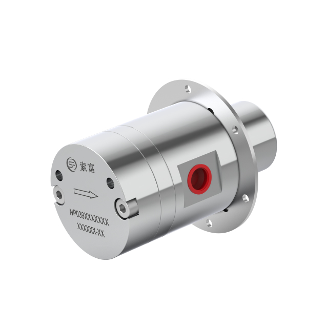
Successful fluid equipment specification requires balancing dynamic variables. Flow, pressure, viscosity, and temperature interact constantly, and ignoring one variable compromises the entire system. Founded in 2010, Suofu is a specialized micro magnetic gear pump manufacturer integrating research, production, and sales to deliver high-precision, zero-leakage fluid handling solutions for demanding applications. Supported by extensive application experience across diverse industries, Suofu also provides customized pump and flow-control solutions based on customers’ actual operating conditions.
Successful fluid equipment specification requires balancing dynamic variables. Flow, pressure, viscosity, and temperature interact constantly, and ignoring one variable compromises the entire system.
Conduct rheological fluid testing to determine precise viscosity profiles across all expected operating temperatures.
Calculate comprehensive system head curves that account for worst-case friction losses during cold startups.
Consult with application engineers to validate custom sizing, material selection, and seal flush plans.
Implement temperature control strategies, such as heat jackets, to maintain consistent fluid properties.
Install Variable Frequency Drives (VFDs) to allow dynamic speed adjustments as process conditions change.
A: Higher viscosity fluids create internal friction, which reduces the flow rate, head, and overall efficiency of centrifugal units. The impeller must work harder to move the thick fluid, requiring more brake horsepower and potentially leading to operational instability if correction factors are not applied.
A: Specific gravity measures fluid density relative to water and dictates the weight of the fluid, directly affecting motor power requirements. Viscosity measures resistance to flow, which determines line friction losses and influences the choice between centrifugal and positive displacement technologies.
A: Elevated temperatures increase a fluid's vapor pressure, which reduces the Net Positive Suction Head Available (NPSHa). If the NPSHa drops below the required level, the fluid vaporizes inside the casing, causing destructive cavitation that damages impellers and seals.
A: Sizing for high-viscosity fluids requires applying Hydraulic Institute correction factors to adjust head, flow, and efficiency. You must also calculate increased friction losses in the piping using the Darcy-Weisbach equation and specify oversized motors to handle the additional viscous drag.
A: Viscous liquids cause high friction losses in suction lines, increasing the Net Positive Inlet Pressure Required (NPIPR). If the system cannot provide adequate inlet pressure, the unit will experience suction starvation, leading to reduced flow, vibration, and potential mechanical damage.